[MAGIC-5S] Manual
Precautions for use
Read and follow the instructions carefully for safe use of the machine. Failure to follow safety precautions may result to injury and/or machine damage.
Intended use: MAGIC-5S is intended for engraving
● Please follow the necessary safety precautions to prevent injury and/or machine damage.
● Please read carefully and understand the instructions below for proper and safe use of the machine.
 |
Failure to follow these instructions may result to machine damage. |
 |
Failure to follow these instructions may result to physical injury or harm. |
Safety Precautions on Electrical System
|
Do not use a damaged power cord or a loose electrical outlet. This may cause electric shock or fire. |
|
Do not plug in two or more devices in a single outlet simultaneously. Overloading your plug sockets may lead to overheating which may cause fire. |
|
Do not pull a plug by the cord. Do not grab a plug with wet hands. This may cause electric shock and burns. |
|
If smoke comes out of the machine, switch off the machine immediately. Do not attempt to repair and/or disassemble the machine, contact our technical support for immediate diagnosis and repair. |
|
Plug the machine into a grounded outlet only. The machine may fail if plugged into an ungrounded outlet, causing property damage, physical injuries, electric shock or fire. |
|
Pull out the power plug when the machine is not in use. |
Safety Precautions on Machine Operation
|
Be sure to use goggles to prevent eye injury from metal chips and dusts. Use a safety mask to prevent exposure from inhalable elements and particles. |
|
Protect your fingers, hands and wrists during operation. The engraving cutter of the machine is sharp and may cause cuts and/or serious injuries if get caught in between the axis. |
|
Be sure to use a dust collector to remove the particles produced during engraving process. Debris like metal chips and dusts may cause serious eye injury if they get stuck in the eye, and may cause respiratory problems if inhaled. |
|
Do not put any foreign objects or any fire hazards on the machine. Never put the machine near or above any heating devices or any flammable materials. |
|
Be sure to place the machine on a firm, flat and level surface. If the machine is not properly installed or placed, the machine may fall, causing physical injury, electric shock or fire. |
|
Be sure to keep the machine out of children’s reach and sight. Children’s curiosity may lead to injury. |
|
Do not disassemble, assemble or modify the machine. This can lead to machine failure and damage, causing fire or electric shock. Please contact our technical support for proper diagnosis and inspection, calibration, and repair. |
|
Avoid spilling water or any liquids on the machine. This may result to machine failure and damage, causing electric shock or fire. If any liquids or foreign objects gets inside the machine, the machine may vibrate excessively then fall. This may cause injury. |
|
Use the machine properly and strictly follow the safety precautions. We will not be held responsible for any damages or injuries caused by mishandling or misuse of the machine. |
|
Avoid using materials that may get caught or jammed in the machine. The engraving and cutting performance and quality of the machine may vary depending on the materials used. |
Safety Precautions on Machine Operation
|
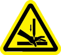 |
Protect your hands, wrists and fingers. Do not let any of your body parts or any foreign objects get caught in the machine during operation. The tools of the machine are sharp, and may cause serious physical injury. |
|
Do not put any foreign objects or any tiny metals inside the machine. This may result to machine failure and damage, causing fire or electric shock. |
|
|
If there is smoke, moisture, oil, dust or water in the place where the machine is installed, do not use the machine. This may cause electric shock or fire. |
|
|
Do not attempt to disassemble and clean the machine if the machine suddenly generates some type of lubricant oil. Contact our technical support immediately. |
|
Other Precautions
|
Do not disassemble or modify the machine. This can cause machine failure and damage. |
|
In order to prepare for an emergency, in case of a sudden machine malfunction or failure, users are strictly advised to not leave the machine unattended while in operation. Users should refrain from engaging in any activity that diverts his/her attention while actually engaged in operating the machine. |
|
Be sure that the machine is placed and kept in a room temperature. If the temperature drops below freezing, the machine may not work property. |
PROPER MACHINE DISPOSAL
 |
The machine contains valuable raw materials and electronic components which must be properly disposed of in equipment disposal containers.
According to European guidelines on proper equipment disposal: |
Laser Specifications
The machine utilizes red laser ‘CLASS 2’ as a guide laser.
- CLASS 2: Class 2 laser is a relatively weak laser that is considered safe for normal operation Its visible beam does not cause any harm or damage on a person’s eye unless deliberately stared into it. It is not a skin or materials burn hazard as well.
| Class | Class 2 |
| Output | 5mW |
| Wavelength | 650nm |
Package Contents
MAGIC-5S provides the following tools and devices. The contents of the package may vary if optional items are purchased.
Take note:
*Cutter, tip and spindle belts easily wear out. Make sure to replace them regularly or as per maintenance schedule.
*All pictures shown are for illustration purpose only. Images may differ from the actual products.
*Be sure to use a safety mask and safety glasses to avoid injury during machine operation.
| Name | Picture | Quantity | Usage |
| Carbide Tip(3Ø) (T31-A09) |
1EA | Tool used for engraving. | |
| L-wrench(1.5mm) (CP-L15) |
1EA | For tightening/unscrewing the bolt. | |
| Additional clamp (CP-51) |
1SET | For holding thick materials in place. | |
| Finger skin (CP-41) |
1SET | For protecting finger chuck. | |
| Flat finger chuck (CP-32) |
3EA | For holding rings in place when engraving the inside or outside. | |
| Round finger chuck (Wide width) (CP-33) |
3EA | For holding rings in place when engraving the inside or outside. | |
| Round finger chuck (Narrow width) (CP-34) |
3EA | For holding rings in place when engraving the inside or outside. | |
| Finger chuck handle (CP-31) |
2EA | To fasten the rotary clamp. | |
| Finger spanner (CP-21) |
1EA | For tightening/unscrewing the finger chuck. | |
| Pin (CP-172) |
6EA | To hold materials with irregular shapes in place. | |
| Ruler (CP-24) |
1EA | For measuring the material. | |
| Power adapter (CP-01&CP-02) |
1EA | Power supply ※Use a grounded outlet only. Do not plug the machine into an ungrounded outlet. |
|
| USB cable (CP-11) |
1EA | For connecting to PC |
*Optional (Sold separately)
Pen finger
(CP-35) 3EA For holding pens in place.
Pen jig
(CP-37) 1EA For holding pens in place.
- Specifications
Operating voltage AC 100~240V
Power consumption 25W
Frequency 50/60Hz
Max. engraving area Flat: 120mm(X) x 100 mm(Y) x 30mm(Z)
Rotary:
Cylinder outside diameter: 40mm
Cylinder inside diameter: 40mm
Weight 21kg
Transfer speed 1 – 36mm/sec (X), 1 – 18mm/sec (Z)
Temperature 15 – 40°C
Humidity 10 - 90%
Purposes Metal marking, Pen marking, Ring marking (inside), Ring marking (outside), etc.
3. Description
(1) Machine
A Power Switch Switches the power on/off.
B Pressure Adjuster Adjusts the pressure of the engraving tool.
• Clockwise: rotate clockwise to increase pressure
• Counter clockwise: rotate counter clockwise to decrease pressure
C Operation key Controls the manual control for regulating engraving operations.
D Engraving tool Secures the tool for engraving.
※To change tools, use a 2mm T-wrench.
E Rotation clamp For holding ring materials in place.
F Multi performance clamp To hold materials with different shapes in place.
G Power Port To connect power adapter to supply power to the machine.
※Use a grounded outlet only. Do not plug the machine into an ungrounded outlet.
H USB Port To connect USB cable to PC.
(2) Clamp
- Multipurpose Clamp
The package includes a multifunctional clamp that is easily assembled, disassembled and transformed into 3 different types of clamps. It can be adjusted according to the height of the material, and can be expanded according to the material’s thickness, size, and shape. This single clamp alone makes engraving on various materials possible without the use of any additional clamps.
How to secure the material in place
Use the clamping knob to secure your material in place. To loosen or widen the clamp, turn the clamping knob counterclockwise; to fasten it, turn the knob clockwise.
Marks may be left on the material if fastened tightly.
How to position the material
Use the vertical ruler bar as an alignment guide to help you position and align your material to the clamp with ease and accuracy. Properly place your material on the clamp then check the alignment.
How to secure the material with irregular shape in place
Use the clamping pins to firmly hold materials with irregular shapes in place. To secure the clamping pins to the clamp, simply insert the pins into the pin holes then fasten them.
How to attach the Additional clamp
The additional clamp is designed with a pair of clamps that are used to hold materials with thick sizes in place like beer bottles.
2) Rotary Clamp
MAGIC-5S’s includes a rotary clamp that is used for engraving the inside and outside of a ring.
How to secure the ring in place
When engraving the outside
Place the ring onto the finger chucks. Rotate the rotary clamp to outward-inward directions to lock and secure the ring in place. Make sure that the ring is firmly attached and locked so it won’t fall off or spin during operation.
When engraving the inside
Insert the ring in between the finger chucks. Rotate the rotary clamp to inward-outward directions to lock and secure the ring in place. Make sure that the ring is firmly attached and locked so it won’t fall off or spin during operation.
If the thickness of ring is not even, mix different sized chuck fingers to hold it.
Finger Chuck Types
There are three types of finger chucks available to match the shape and size of the ring.
Flat chuck finger Round chuck finger (wide) Round chuck finger (narrow)
How to replace finger chucks
Choose the appropriate finger chucks for your ring. Insert the finger chucks into the holes then fasten them tightly with the use of a finger chuck spanner. ※The finger chuck spanner is included in the package.
How to secure the bangle in place
Place three bangle adapters in the rotation clamp, and tighten the chuck finger in front of the bangle adapters. Open the rotation clamp to match it to the bracelet size, and insert the bracelet until it clicks into the chuck finger. Use the chuck handle not to make bracelet come out or spin.
(3) Keypad
Stop	Stops/cancels marking.
Vise	When operating vise:
Long-press: long-press and hold the button to enter tool settings mode.
Short-press: short-press the button to move the clamp back and forth.
Flat chuck finger Move to flat finger chuck origin: press the button to move the laser pointer to flat finger chuck origin.
Save the origin: once the laser pointer is moved to flat finger chuck origin, press the button for 2 seconds to save the changed origin.
Round chuck finger Move to flat finger chuck origin: press the button to move the laser pointer to round finger chuck origin.
Save the origin: once the laser pointer is moved to round finger chuck origin, press the button for 2 seconds to save the changed origin.
Pointer Turns laser pointer ON/OFF.
Start Upon transferring the engraving data and specifying the engraving area, long-press and hold the button for more than 2 seconds to start engraving.
Save After changing the tool settings, long-press and hold the button for more than 2 seconds to save settings.
Direction key
(A) When rotating the rotary vise:
Rotation automatically stops when it reaches 0°, 90°, 180° or 270° locations.
Direction key
(Z) Move Z axis up and down
Direction key
(X, Y) On stand-by mode:
X-/X+ moves X axis left or right.
Y+/Y- moves Y axis up or down.
On engraving mode:
Checks and moves the engraving position
Medal / Pendant Moves the Multi performance clamp.
Ring Outside Moves to ring outside marking position of the rotary clamp.
Ring Inside Moves to ring inside marking position of the rotary clamp
(4) Switching Tools
Do not let any of your body parts or any foreign objects get caught in the machine during operation. The tools of the machine are sharp, and may cause serious physical injury.
As shown below, insert the 1.5mm wrench into the fixing bolt. Turn the wrench to the left to unscrew bolt. To prevent the tool from falling to the floor, grab tool with your hand then pull it out. Once the tool is removed, replace it with a new tool then secure it using a wrench for tightening bolts. ※See package contents
When unscrewing the tool fixing bolt, hold the tool with your hand while unscrewing to avoid the bolt from dropping on the floor.
(5) Pressure Adjuster
When engraving with a diamond/carbide tip, adjust the depth by pressure. This has the same effect as assigning the engraving depth when creating a tool path. To increase pressure, turn the pressure adjuster counterclockwise; to decrease pressure, turn it clockwise
4. Installation
※ Please follow the instructions below for proper installation of the machine, software and other devices.
※ The software program requires Windows OS 7 or higher.
(1) Machine Installation
MAGIC-5S cannot operate alone as a desktop engraver. It cannot proceed to engraving and cutting operation without the use of a computer and a software.
The machine should be connected to a personal computer for the machine to operate. The software provided along with the machine must be installed to the computer to run the program for engraving, cutting and marking.
How to install the machine
- To start the machine, plug its power cable into a grounded outlet. ※See precautions for use for safety.
- To connect the machine to the computer, plug in the USB cable on the back of the machine then on the computer’s USB port.
(2) Program Installation
System requirements
-Supported devices: PC
-Operating system: Windows 10 or higher
-Processor: Intel® Pentium® CPU or higher
-Memory: 4GB or more
How to install the software
-
Insert the USB into your computer`s USB port. A notification will pop-up on your screen regarding installation. ※USB is included in the package.
-
Follow the instructions below to install the software.
-
Follow the steps in order until installation is complete.
-
In case program installation won’t automatically run upon inserting the USB into your computer, go to My Computer’s USB drive then run Install program.
-
Setup wizard.
2. Select installation folder. -
Confirm installation.
3. The file is copied onto the hard disk. -
USB driver setup wizard.
5. Check I accept the agreement, then click Next. -
Check Status: Ready to use, then click Finish.
7. Click “Run MagicEngrave” button to complete program installation.
-
Program Description
Once the installation is completed, the following icon will appear on your desktop. The description of the icon is as follows:As a design & marking software program, it features the following functions: marking design, marking option, Toolpath setting, transfer of Toolpath data.
5. Operation of the Marking Machine
MAGIC-5S performs self-diagnosis upon turning ON. During self-diagnosis, the machine checks the following in order:
(1) Self-diagnose Procedures
- If a certain axis is detected by the sensor, it moves away from the detected area.
- Checks probe sensor and returns to the Origin point
- Checks Z-axis sensor and returns to the Origin point
- Checks Y-axis sensor and returns to the Origin point
- Checks X-axis sensor and returns to the Origin point
- Confirmation sound and standby
If no problem is found, it goes into standby mode with a confirmation sound.
(2) Marking Procedures
-
Turn on the marking machine.
-
Run the program to connect it to the machine.
-
Place your material on the work area.
4. Make your design then create a toolpath.
-
Click the Machine button to send the marking data.
-
Press start button on the machine to begin the engraving process.
Before Using the Program
The property of the object (i.e., size, shape, position, etc.) can be changed or modified when the object is selected.
The mouse cursor display changes depending on the function (i.e., text input, resize, select, etc.).
Program Usage Description
Shown below is the window that will appear once the program starts running. Icons displayed on the window may vary depending on the selected mode. The name of each category is as follows:
◈ Program Screen
◈ Text Input Mode
Click Text Input button on the upper center of your screen or double-click on the composition area to input text.
◈ Object Selection Mode
After entering the text, use Selection button with your mouse or right-click the text on the composition area to switch to selection mode. To switch to text input mode, double-click on the selection mode.
◈ Object Rotation Mode
To activate object rotation mode, double-click the text while in selection mode.
- Toolbar
◈ Alignment Tools
Line/Curve
Click a certain point then hold your mouse and drag to make a dot line appear. Designate the distance then right-click to create a straight line. Then, press “Ctrl” key on the keyboard and move the mouse to create a horizontal line or a vertical line.
Click a certain point and designate a distance. Hold your mouse and drag to make a curve appear. Right-click to create a curve.
Circle/Oval/Pie
Click the work area then hold your mouse and drag to designate the size of a circle. Press “Shift” key on the keyboard then drag your mouse to create a perfect circle.
Click button on the circle object property window to convert to arc. The start/end of an angle of an arc can be assigned, or adjusted by dragging the start/end with the mouse. Click button to create a reversed arc image.
Click button on the circle object property window to convert to pie (a filled arc). The start/end of an angle of a pie can be assigned, or adjusted by dragging the start/end with the mouse. Click button to create a reversed pie image.
Rectangle
Click the work area then hold your mouse and drag to designate the size of a rectangle. Press “Shift” key on the keyboard then drag your mouse to create a square.
The curvature of each edge can be assigned on the rectangle object property window. Or, by dragging the edges of the rectangle with the mouse, the edges convert into round corners.
Click button on the rectangle object property window to adjust the curvature of each corner individually.
Polygon
Click the work area then hold your mouse and drag to designate the size of a polygon. The number of vertices can be assigned on the polygon object property window.
Mirror
Produces mirrored image.
Rotation
Double-click to select rotation then hold your mouse and drag to rotate the image.
Invert color
Inverts the color of the image.
90˚CW
Rotates the image by 90˚.
Horizontal center in page
Vertical center in page
Center in page
Alignment options
Alignment Align to the left of base object
Align to the center of base object
Align to the right of base object
Align to the top of base object
Align to the center of base object
Align to the bottom of base object
Adjust horizontal gap Align horizontal gap between objects evenly
Adjust vertical gap Align vertical gap between objects evenly
Same size Make same width
Make same height
Make same size
Alignment Horizontal center in page
Vertical center in page
Order Bring to front
Send to back
◈ Object Tools
Barcode
Create a barcode object.
Design sample
Import design sample or save current object as design sample.
What is a Design Sample?
Design sample is the object saved in the design sample library. Design samples can be easily and quickly imported from the design sample library and edited freely.
Selection
Use selection mode to modify the object’s property or adjust its size and position. To use, click the object created in the work area then adjust its property. To input text, right-click.
Object selected No object selected
Text input
To input text, click button then click the object in the work area or, simply double-click to enter text.
Cursor (Text input mode)
To modify the object’s font style and size, click button then hold and drag the character/s with the mouse.
Click button to create a text box. Then hold and drag the mouse to adjust the size of the text box. The size of the text box limits the number of character input.
A blinking cursor display indicates ‘enter text.’
Or, go to Menu → Insert → Text box.
Circular text
Create text objects along a circle.
Drawing pen
Hold and drag the mouse to draw character/s to create an object with the use of drawing pen. The drawing line’s thickness can be adjusted in the drawing object property window.
Outline stroke of object
Apply outline stroke to the object.
Auto Inverts Color
The color of one object auto inverts to opposite color to contrast the other object’s color when overlapped.
Click button then select the object to be placed over the target object. Upon pacing the selected object over the target object, the selected object auto inverts to an opposite color.
For texts, click the button then drag the selected text and place it over the target object.
If the color is not inverted, go to Layout menu → Order → Top Most then place the selected object over the target object.
Image
Import image (e.g., bmp, jpeg, gif, png … etc.).
Line eraser
Erase the line of a created object.
Click the object to be erased then hold and move the mouse over the line to erase. (Take note that some objects may not be erased with the Line eraser tool).
◈ Toolpath
※Please refer to 4. How to engrave for each toolpath for details.
What is a Toolpath?
Toolpath is a path where the tool passes by for marking.
Toolpath is usually displayed in red color and the marking tool moves along the path as it engraves.
◈ Origin Point Setting Tools
Left top origin point Left bottom origin point
Center origin point
◈ Basic Tools
New document
Open a new page.
Open
Open a file in “*.dgn” file format.
Select a file on the “Open” window and click “Open” button.
Save document
Save the design created on program as “*.dgn” file format.
Choose the location (folder) in which the file will be saved then enter the file name before clicking “Save” button.
Print
Print the design created on program.
Cut
Cut the selected object. Click cut on the menu or press Ctrl+X on the keyboard.
Ctrl + X Ctrl + V
Copy
Copy the selected object. Click on the menu or press Ctrl+C on the keyboard.
Ctrl + C Ctrl + V
Duplicate Horizontally or Vertically
Click icon in toolbar to multi-copy the same object at once, or go to Edit → Copy → Duplicate Horizontally or Vertically….
Paste
Paste the cut or copied object. Click on the menu or press Ctrl+V on the keyboard.
Undo / Redo
-Undo: To reverse the action recently done.
Go to Menu → Tool → Option → General to adjust the number of undo action.
-Redo: To restore the action that was previously done.
◈ Zoom in/out/move Tools
Zoom in
The screen appears much larger and nearer.
Zoom out
The screen appears much smaller and farther.
Zoom in/out ratio
Select the desired screen ratio. The size of the screen will appear base on the selected ratio.
Magnifier
Select a certain spot on the object then hold and drag the mouse to enlarge it.
Fit to object
Enlarge the object to fill in the screen.
Fit to page
Adjust the page size to see the whole work area.
Panning
Drag the screen with the mouse to move it.
2. Text Object Property
Select the text object to see its property. The property of the object will appear on the left side of the screen.
Font
Designate font. Click “Preview” button or the arrow beside it to designate font.
*Right-click the font preview window to see menu. Click “Show Font List” then designate the fonts to be shown in preview.
Size
Adjust the size of the selected text. Click size button to adjust the size of the font or the arrow beside it.
Bold
Change text style to bold.
Italic
Change the text style to italic.
Reduce or increase font weight by one level
Adjust the weight of font.
Symbol
Insert symbols.
[Text change]
Modify the entered text. Edit the text on the text field or click button to add long texts.
Text Alignment
Align to left
Align characters to the left in the text box.
Align to center
Align characters to the horizontal center in the text box.
Align to right
Align characters to the right in the text box.
Both
Align characters evenly to both sides in the text box.
Align to top
Align characters to the top in the text box.
Align to center
Align characters to the vertical center in the text box.
Align to bottom
Align characters to the bottom in the text box.
Horizontal text
Arrange characters horizontally.
Vertical text
Arrange characters vertically.
Move the selected character horizontally (left, right).
Move the selected character vertically (up, down).
Adjust the width of the selected character.
Rotate the selected character.
Position/Size
Designate the location of the selected object
Designate the size of the selected object
Click “check” to maintain the same ratio for the object’s width and height. Click “uncheck” to adjust the object’s width and height separately.
Line and Fill Shape
Line thickness of the selected object
Line type of the selected object
Line color of the selected object
Color filled inside of the selected object
Shape filled inside of the selected object
3. Rotation Tool Property
Rotation
Designate the rotation angle of the selected object. Enter the desired angle of rotation or click the up/down arrow buttons.
Rotate selected object according to the angle entered.
Add a new object and rotate it according to the angle entered.
4. How to Engrave for Each Toolpath
What is a Toolpath?
Toolpath is a path where the tool passes by for marking.
Toolpath is usually displayed in red color and the marking tool moves along the path as it engraves.
Cut-out toolpath
Creates a toolpath that will cut out the selected object. The toolpath boundary will be wider than the boundary of the selected object depending on the thickness of the tool. *This toolpath must be used when cutting.
Outline toolpath
Creates a toolpath that will engrave the outline of the selected object.
Hatching toolpath
Creates a toolpath that will engrave the inside of the selected object.
Single line toolpath
Creates a toolpath that will engrave the center line of the selected object.
“Single line toolpath” process may cause deviation on center line.
It is recommended to use fonts with thinner lines to reduce deviation.
Boundary-line toolpath
Creates a toolpath that will engrave the boundary of the selected object.
Inline toolpath
Creates toolpath that will engrave inline of the selected object.
The toolpath is created within the borders of the selected object.
V-cut toolpath
Creates a toolpath that will engrave V-cut groove.
Convert object to toolpath
Convert the selected object to toolpath. It’s not necessary to set toolpath settings each time. It will be automatically set to its preset values.
Photo impact engraving toolpath
Creates a toolpath that will engrave an image with dots.
Scan-line toolpath
Creates toolpath that will engrave inside area of the selected object’s boundary.
“Scan line toolpath” may appear similar to “Hatching toolpath” but it is specifically used to engrave on logos, patterns or objects with larger areas.
Contour line toolpath
Creates a toolpath that will engrave the selected object with contour lines.
Photo halftone engraving toolpath
This converts an image into a half-toned image and engraves the object in dots or horizontal lines using a V-cut tool. This process is only applied to engraving machines with rotating-spindle function like Magic E7, E4 etc.
                 [Dot]
                          [Horizontal Line]
What is Half-toned Engraving?
Half-toned engraving converts light and dark areas of a picture or an image into lines or dots in different sizes to express a fine image.
Simulate toolpath processing
Click this button to see the predicted image result of the toolpath processed by the selected tool.
Show toolpath only
Click this button to make the toolpath the only visible object on the screen (while all the other objects are temporarily hidden). Click this button again to reveal the other objects.
- Create Toolpath
Tools in Tool option may vary according to types of models.
Tool
Designate a tool to be used for engraving. Each tool setting value can be changed by clicking Edit or Add button.
Preset Hatching gap, depth, engraving speed and others are pre-set for each engraving option. It is not necessary to assign each value every time as the values is automatically pre-set. Each value can be changed by clicking Edit or Add button.
Direction The following hatch lines are applied to hatching toolpath only:
- : A tool path is created in the horizontal direction
- A tool path is created in the vertical direction
- A tool path is created in the left diagonal direction
- A tool path is created in the right diagonal direction
- A tool path is created in the cross hatched direction
※ These toolpaths are not recommended to be applied to materials with plated surfaces as they may cause possible damage to the material.
Option Depth Engraving: Refers to the applied pressure and not the actual engraving depth. The higher the pressure is, the deeper it imprints.
Cutting: Refers to the actual engraving depth when using rotary tools like end mills, V cutters, etc.
Z Pitch Designate the depth when cutting the engraving depth little by little. This option is necessary when cutting thick materials with a thin tool.
Hatching gap Designate hatching gap.
0.1mm 0.2mm 0.3mm
Margin Designate a margin between object outline and toolpath.
0.1mm 0.2mm 0.3mm
Engrave outline If this option is checked, a toolpath with an outline is created. If unchecked, a toolpath without an outline is created.
with outline without outline
Speed XY speed Designate a speed at which XY axis will move during the engraving.
Z speed Designate a speed at which Z axis will move during the engraving.
Engraving speed is displayed in colors according to tools or engraving options.
Move
Option Z clearance This designates the height to be applied for the clearance between the tool and the surface of material when moving to another engraving location.
When moving to another engraving location, it is necessary to lift Z axis to prevent the tool from coming in contact with the material surface before moving.
Z dwell
time This designates no-load rotation time of end-mill and V-cutter after they reach the target depth and before moving to X, Y axis point. It is possible to damage the tool as rotation speed reduces while engraving. Set up the Z-dwell time to recover the full rotation speed before engraving.
✽Recommended time: 0.5 ~1 second.
Transmit Toolpath output window is displayed
(1) Tool: Add/Delete/Edit
Check “Edit” button to see Add/Delete/Edit buttons.
Designate a name for the tool to be added along with its type and other options like tip width, then click “OK” button. The tool will then be added to the tool selection list.
Select a tool to be deleted then click “Delete” button to remove the tool from the list.
Select a tool to modify then click “Edit” button. Click “OK” button to save the modified value.
(2) Engraving Option: Add/Delete/Edit
Check “Edit” button to see Add/Delete/Edit buttons.
Enter a name then set the hatching gap, engraving depth and speed. Click “OK” button and the option will be added to the selection list.
Select an option to be deleted then click “Delete” button to remove the option from the list.
Select a tool to modify then click “Edit” button. Click “OK” button to save the modified value.
6. Toolpath Object Property
Select the toolpath object to see its property and/or to adjust its speed and depth. The toolpath object property will appear on the left side of the screen.
Depth Engraving: Refers to the applied pressure and not the actual engraving depth. The higher the pressure is, the deeper it imprints.
Cutting: Refers to the actual engraving depth when using rotary tools like end mills, V cutters, etc.
Z pitch Designate the depth when cutting the engraving depth little by little. This option is necessary when cutting thick materials with a thin tool.
XY speed Designate a speed at which XY axis will move during the engraving.
Z speed Designate a speed at which Z axis will move during the engraving.
Z clearance
This designates the height to be applied for the clearance between the tool and the surface of material when moving to another engraving location.
When moving to another engraving location, it is necessary to lift Z axis to prevent the tool from coming in contact with the material surface before moving.
Z dwell time This designates no-load rotation time of end-mill and V-cutter after they reach the target depth and before moving to X, Y axis point. It is possible to damage the tool as rotation speed reduces while engraving. Set up the Z-dwell time to recover the full rotation speed before engraving.
✽Recommended time: 0.5 ~1 second.
Engrave twice Engrave the design twice.
7. NC Data Output
(1) Transfer the Toolpath Data after Creating a Toolpath
Select a toolpath then click the “Engraver” button on the top-right of the screen to transfer the data of the selected toolpath to the MAGIC-5S machine.
On the NC output window, select a measuring method and other options, then click “Start Engraving” button to start transferring the toolpath data to the selected machine.
Toolpath order The toolpaths are put in order if two or more toolpaths are selected for engraving. The order can be modified by clicking Up/Down button on the right.
Surface height
measurement Surface height Measures material height only.
Skip	Skips material’s height measurement and allows the use of the previous height measurement data if the material has not been removed from the clamp during the previous engraving process.
Horizontal
slope Measures material’s horizontal gradient.
Vertical
slope Measures material’s vertical gradient.
Surface slope Measures material’s top, bottom, left and right gradient.
Material surface Flat Engraves flat-surfaced materials.
Uneven Engraves curve-surfaced materials.
Multiple engraving Engraves materials repeatedly in constant vertical/horizontal intervals.
✽A vise is used for this automatic engraving and available for separate purchase.
Simulate engraving Displays engraving simulation on the material by using laser pointer to ensure that it follows a correct path.
Adjust engraving position Select this option to re-adjust the engraving location. The laser pointer then adjusts to the engraving location before engraving. If this option is not selected, engraving process will initialize immediately.
Move to vise automatically Move automatically to the flat or rotating vise based on the selected template.
Touch-Mark-Free Measurement Prevents height measurement points from leaving any marks.
Turn on External Device Enables automatic external device operation.
✽ “NC output” window when selecting ring template.
Surface height Measures material height.
Multi-point-measurement Measures material height by dividing the whole material into several parts
(up to 5 times)
Outside Engraves the outside of the ring.
Inside Engraves the inside of the ring.
Place the material on the flat chuck finger.
Place the material on the round chuck finger
(2) Transfer the Toolpath Data after Entering Text
Transfer the text data to the engraving machine without creating a toolpath. After creating a text design, click button on the right top of the screen for immediate marking.
Marking Process
-
Measure the size and height of your material.
-
Place your material at the center of the clamp.
-
Select a template that matches the shape or type of your material from the template category. Enter the size of your material then click “OK” button.
Maintain original size The actual size of the registered template is loaded; not the size entered.
Locate to original
position The template is loaded to where it was initially created. If this option is selected, the template is loaded at the center of work area.
Fit page size to template The size of the page is adjusted to the size of the template.
4. The selected template will appear on the screen. Click Text input button then click at any target location to enter text.
- Once the text is completed, click Selection button on toolbar. Enable the object selection mode to select the entered text then modify the size, font and thickness of the object. Lastly, click Center in page button to position the object at the center of the work area.
6. Upon completing the design, click Hatching toolpath.
✽Click icon on the top right of the screen for immediate marking without creating a Toolpath.
- Select an engraving option and tool from “Hatching Toolpath” window and if necessary, designate gap and depth before clicking “Create Toolpath” button.
-Scan line toolpath- -Hatching toolpath-
For better engraving quality on large areas (e.g., large fonts or images) use “Scan line toolpath.” Although this may require more time to process.
8. Toolpath object is created.
-
Click button.
-
Once “NC Output” window appears, specify how the engraving material is measured then click “Start Engraving” button.
11. Once the tool is positioned to the center of the material and the laser pointer turns on, use the direction key buttons to position the laser pointer to the engraving area. The area that the laser pointer points to is where the actual engraving takes place.
Press the direction key buttons to move the laser pointer to the left, top, right and bottom areas of the engraving area. (Long press to move the laser pointer farther). Check if the laser pointer points to the area on the material where you want to engrave. If the laser pointer is out of range, adjust the position using the direction keys.
The laser pointer automatically points to the area where the engraving takes place (based on the target location on the work area).
When the direction key is pressed, the laser pointer moves to the area to be engraved (left, top, right or bottom) from its target location. If the engraving area needs to be adjusted to the left, press key to move the pointer to the left.
- After positioning the laser pointer and determining the location of the engraving area, long-press and hold button (for more than 3 seconds) until it beeps to confirm that the machine is ready to engrave.
Ring Inner/Outer Marking Process
- Measure the width and diameter of the ring.
<Outer marking – Ring outside size> <Inner marking – Ring inside size>
- Insert the ring into the chuck finger (as shown below) then tighten the rotation clamp to firmly secure the ring.
Ring outer engraving Ring inner engraving
Object position
Engraving direction
The direction of the characters to be engraved on the ring is shown in the picture below. Check the target location (where you want your characters to be engraved on the ring) then firmly secure the ring.
3. Double click “Ring” template in the object property window. When Insert Rotary Object Template window appears, select one engraving option: outside or inside. Then enter the width and diameter of the ring and click “OK.”
-
The template will appear at the center of the screen. Select Text Input on the toolbar then click at any target area on the work area to enter the text to be engraved.
-
After entering the text, click Selection on the toolbar to enter the object selection mode. Select the text, then edit its size and font. To place the text at the center of the work area, click Center in Page button.
What is Handle for adjusting gaps between characters?
Handle for adjusting gaps between characters is a function that adjusts gaps between characters by dragging characters to target positions.
6. Upon completing the design, click Hatching Toolpath button.
✽Click button on the top right of the screen for immediate marking without creating a Toolpath.
-
The “Hatching Toolpath” window will appear (as shown in the picture below). Select the tool, toolpath gap and depth then click “Create Toolpath” button.
-
The “Toolpath” object is created with red lines marked or filled on each text (as shown in the picture below). Scroll up the mouse wheel to zoom in the image of the toolpath object to check the line style. You may delete the toolpath object and create a new one if the toolpath is not your preferred style.
[Toolpath creation] -
After selecting your preferred toolpath, click button.
-
Once “NC Output” window appears, specify how the engraving material is measured then click “Start Engraving” button.
Surface height Measure material height.
Multi point measurement Measure material height by dividing the whole material into several parts (up to 5 times)
Outside Engrave on the ring’s ring outer diameter.
Inside Engrave on the ring’s ring inner diameter.
Place the material on the flat chuck finger.
Place the material on the round chuck finger
-
Once the tool is positioned to the center of the material and the laser pointer turns on, use the direction key buttons to position the laser pointer to the engraving area. The area that the laser pointer points to is where the actual engraving takes place.
Press the direction key buttons to move the laser pointer to the left, top, right and bottom areas of the engraving area. (Long press to move the laser pointer farther). Check if the laser pointer points to the area on the material where you want to engrave. If the laser pointer is out of range, adjust the position using the direction keys.
The laser pointer automatically points to the area where the engraving takes place (based on the target location on the work area).
When the direction key is pressed, the laser pointer moves to the area to be engraved (left, top, right or bottom) from its target location. If the engraving area needs to be adjusted to the left, press key to move the pointer to the left.
- After positioning the laser pointer and determining the location of the engraving area, long-press and hold button (for more than 3 seconds) until it beeps to confirm that the machine is ready to engrave.
Photo Marking
What is Photo Marking?
Photo marking is a marking method that marks the shade of an image with dots.
-
Place the material on the clamp.
-
Click Image to import an image for marking.
-
Adjust the size and location of the image.
-
Clipping Mask feature enables clipping or cropping of the target image. Drag the mouse over the image then create a shape.
-
Drag and hold the mouse to select the target image or select Menu → Edit → Select All.
-
Then select Menu → Transform → Make Clipping Mask. Only the cropped image (target image) remains.
The original image is saved; not deleted or cropped out.
7. Click Photo Impact Engraving Toolpath button.
✽Click button on the top right of the screen for immediate marking without creating a Toolpath.
- Adjust marking options in photo marking option window.
✽ The black area is not engraved; only the cropped image.
During photo marking process, the brighter area (white area) of an image is not visibly expressed with dots unlike the darker area where dots are highly visible with higher marking quality. Therefore, it is recommended to adjust the brightness of an image to darker. Normally, a dot ratio of 10-20% provides the best marking quality for a portrait. Take note that the image’s optimal conditions vary depending on the brightness of background of the image. Check image preview then adjust the image’s brightness and dot ratio. If ‘image adjustment’ is confusing, click “Recommend the best” button to automatically adjust the image.
9. Click “OK” button to create a toolpath for photo marking. Set the laser marking option then click Engraver button.
During marking process, the white area of the image appears with dots. The image result of the toolpath is shown as a negative image.
-
Once the tool is positioned to the center of the material and the laser pointer turns on, use the direction key buttons to position the laser pointer to the engraving area. The area that the laser pointer points to is where the actual engraving takes place.
Press the direction key buttons to move the laser pointer to the left, top, right and bottom areas of the engraving area. (Long press to move the laser pointer farther). Check if the laser pointer points to the area on the material where you want to engrave. If the laser pointer is out of range, adjust the position using the direction keys.
The laser pointer automatically points to the area where the engraving takes place (based on the target location on the work area).
When the direction key is pressed, the laser pointer moves to the area to be engraved (left, top, right or bottom) from its target location. If the engraving area needs to be adjusted to the left, press key to move the pointer to the left.
- After positioning the laser pointer and determining the location of the engraving area, long-press and hold button (for more than 3 seconds) until it beeps to confirm that the machine is ready to engrave.
Pen Engraving Process
-Tailstock is sold separately.
-
Measure the width and diameter of the pen.
-
Secure the pen to the engraver by using a pen clamp.
The pen jig may differ depending on model types. The instructions are almost the same for all types of engravers regardless of the type of jig used. Be sure to follow the instructions below to determine the correct positioning of the pen when engraving.
3. Select a pen template in the object property window. Enter the width and diameter of the pen then click “OK” button.
-
Once the template appears, click Text Input on the toolbar. Click the work area then enter text.
-
After entering the text, click Selection on the toolbar to enter object selection mode, then adjust the size and font of the text. Click Center in Page button to place the object at the center of the work area.
-
Upon completing the design, click Hatching Tool path.
✽Click button on the top right of the screen for immediate marking without creating a Toolpath. -
Select engraving option and tool from the “Hatching Toolpath” window. If necessary, designate the hatching gap and depth then click “Create Toolpath” button.
-
“Toolpath” object is created.
9. Click button.
-
Once “NC Output” window appears, specify how the engraving material is measured then click “Start Engraving” button.
-
Once the tool is positioned to the center of the material and the laser pointer turns on, use the direction key buttons to position the laser pointer to the engraving area. The area that the laser pointer points to is where the actual engraving takes place.
Press the direction key buttons to move the laser pointer to the left, top, right and bottom areas of the engraving area. (Long press to move the laser pointer farther). Check if the laser pointer points to the area on the material where you want to engrave. If the laser pointer is out of range, adjust the position using the direction keys.
The laser pointer automatically points to the area where the engraving takes place (based on the target location on the work area).
When the direction key is pressed, the laser pointer moves to the area to be engraved (left, top, right or bottom) from its target location. If the engraving area needs to be adjusted to the left, press key to move the pointer to the left.
- After positioning the laser pointer and determining the location of the engraving area, long-press and hold button (for more than 3 seconds) until it beeps to confirm that the machine is ready to engrave.
Engraving Curved Materials
Scratch on the surface of a curved material is likely to be caused by the tool touching the surface of the material when it moves. This can be avoided by entering the thickness of the material’s surface to set the Z-movement height automatically.
-
Create a toolpath then click button.
-
Once “NC Output” window appears, click “Uneven” to see different kinds of curved materials. Select a shape that resembles the shape of the material then enter its thickness (the thickness of the area to which the engraving is applied) then click “Start Engraving” button.
Layout of Text in a Circle
Texts can be arranged around a circle by using circular text object.
Circular Text
Click button to display “Circular Text” window. Assign a direction and an angle, enter the text and size, then click “OK” button.
Circular Text- Top/Bottom
Adjusting layout angle
Drag the first character R or last character y in the text to adjust the angle of the layout.
Drag other characters with the mouse to adjust the distance to the center of the circle.
Layout of Text in a Curve
-
Click the Line/Curve button.
-
Left-click to display the dotted lines then designate a distance. Drag the mouse to make a curve appear then right-click to create one.
-
Select “No Line” on the “Line and Fill Shape” window on the object property window.
-
Click Text Input button then move the mouse cursor to the curve line. The cursor will change to text cursor as shown below.
-
When the cursor changes to text, click the curve line then enter the text.
Text Change
The content of a text can be changed by using Text Change feature.
Open a saved design sample, file or select the text objects entered on the work area. Click Text change button or right-click with the mouse then select Text Change on the menu. Or, select Menu → Text → Text change.
Change the content in the “Text Change” window then click “OK” button. The modified text will be shown on the screen.
Template Creation
Template is an image that corresponds to the material to be engraved by 1:1 ratio. Load a template similar to the shape of the material to be engraved then enter the text. This allows you to easily and conveniently position your text and determine its size. Templates such as circle, heart, square and diamond are available in the program, and users can freely add more templates. Templates can be created by using graphic programs like Illustrator, Photoshop and CorelDraw, or by loading images in SVG file format, jpeg, bmp, png, etc.
Creating template #1
-
Select Menu → Template → Create Template from Image.
-
"Create Template from Image” window will appear.
3. Select the image file (jpeg, bmp, png and etc.) from the “Open” window then click “Open” button.
- Enter the size of the template. Check “Save” to save the image as a template for later use then enter the file name. Click “OK” button to load the image as a template. The image will be saved as a template in the template library.
Creating template #2
-
Click Image button to open an image file.
-
Select Menu → Template → Save Selected Object as Template.
Enter a new template name in “Input” window then click “OK” button.
3. The saved template is added to the template library.
The saved template in the “Save Selected Object as Template” menu is saved based on the size designated on the screen. When loading a template, check “Maintain Original Size” so the template will be loaded based on the original size designated when the template was saved.
✽ Templates can be added or deleted. “Add” or “Delete” option can be selected by right-clicking in the template category window.
Saving as Design Sample
Edited texts, contents or designs can be saved as design samples for future use.
Saving as design sample #1
-
Edit contents and select the objects.
-
Click File Menu → Save as Design Sample then select a folder or create new folder.
Enter the name then click “Save.”
Saving as design sample #2
-
Select the objects then click Design Sample button. Select a folder from the design sample library window to save the created design.
-
Click Save selected image as sample or right-click the design sample image then click “Save Selected as Design Sample” on the menu.
3. Enter the name of the design created then click “OK” button. The design will be saved in the design sample library.
✽ Right-click in the design sample window to see more features. The design sample can be deleted by
right-clicking in the design sample window then select or “Delete” on the menu.
Auto Change of Serial Number
Use this function when changing numbers by certain unit.
-
Edit the font and size of text object with a number then press “Alt+N” key on a keyboard, or select Menu → Text → Serial Number → Advance Serial Number to change the number automatically.
-
Select Menu → Text → Serial Number → Serial Number Option then enter a unit from the “Serial Number Auto Advancing Option” to change the serial number based on the assigned unit automatically.
3. If the serial number is not consistent, select Menu → Text → Serial Number → Load Serial Number.
Enter serial number in the “Lines to export” field or click “Load File” button to load from a file (.txt or .csv file format). Once the serial numbers are loaded, click “Export to object” button. The text on the selected text object is automatically changed, and the serial number is deleted from the list. The deleted numbers will be shown in the “Exported Lines.”
Serial numbers can be loaded from a file separated by a comma (.csv) or text file (.txt).
Each row of the file is recognized as one serial number, and the contents of each row separated by a comma are shown in the next line.
Loading and Editing Image
- Loading an image
This program provides a function to load various types of image files. Supported image files are as follows.
BMP Windows or OS/2’s bitmap graphic file
GIF CompuServe graphic file
JPG/JPEG JPEG bitmap graphic file
PNG Portable Network Graphics bitmap graphic file
PCX Z Soft PC paintbrush bitmap file
TIF/TIFF Tagged Image File Format bitmap file
WMF Windows meta file
Image file can be loaded through the following methods.
-
Select Image on the toolbar or select Menu → Insert → Image.
-
When “Open” window appears (as shown in the picture below), select the image to load then click “Open” button.
3. Drag the work area with the mouse to load the image according to desired size.
- Converting and editing image
The machine can only engrave single-color images; not multi-color images. Multi-color images should be converted to single-color (1 bit) image.
Converting to single-color image
- Select the image you want to convert. Click “Convert” button in the image object window then select “Monochrome (1bit).”
Or select the Transform menu → Bitmap → Mode → Monochrome (1bit).
2. When “Color Image to Black & White” window appears, move the slider to adjust the level of color then click “OK” button.
Editing image
Loaded image can be edited via “Paint” program in Windows.
Select the image object to be edited then right-click to select “Edit” or, select Menu → Transform → Bitmap → Edit.
Click OK to run Windows Paint program.
Then “Image Edit Notification” will appear.
Once editing is completed, click “Save” from Paint File menu then close the program to apply the changes.
Import a File in SVG format
MagicEngrave supports vector graphic files in SVG format. If a design is created in programs like Illustrator or CorelDraw, the design can be loaded as long as it is saved as SVG file.
-
Select File menu → Save As from Illustrator program to save a file in SVG format.
-
When SVG option window appears, click “OK” button to save changes.
3. Click button to load the SVG file.
-
Or select Menu → File → Import… to import a file.
-
Once the file is imported, click the work area to display the image.
Calibration
※ The machine is initially set up at the factory. Please contact your reseller first before making any changes to the settings of the machine.
※ Only carbide and diamond tools can be calibrated. Do not calibrate tools such as endmill and cutter.
※ Be sure to unlock the pressure lock when calibrating the machine. Nose, tool and material can be damaged if the head is fixed or when the pressure lock is locked.
-
Touch Sensor (Tool Calibration)
-
Place and secure the material on the clamp.
-
When attaching the tool, keep the length short as possible.
-
Press (Flat) on operation button to move the tool to the clamp.
-
Press button to enter tool calibration mode.
-
The tool will be lowered and come in contact with the material and will be placed in the center of the clamp.
-
Lower the tool by loosening the fixing bolt of the tool with a wrench, or lift the material with your hand to make the tool and material come in contact as shown in the picture below.
-
Long-press and hold button (for more than 3 seconds) until it beeps to confirm that the setting is saved then the tool will measure the material’s height.
-
Laser Pointer Calibration
Multipurpose Clamp
-
Place and secure a flat material on the clamp.
-
Press button to enter laser pointer calibration mode.
-
The tool draws a cross (+) line on the material and the laser pointer is turned on.
-
Move the laser pointer to the center of the cross by using the direction keys then press button.
-
The laser pointer moves closer to the material to calibrate the laser pointer’s origin. Move the laser pointer to the center of the cross by using the direction keys on the engraving machine then long-press and hold the button (for more than 3 seconds) until it beeps to confirm that the setting is saved.
Rotation clamp
-
Secure the ring to the rotation clamp.
(When setting the laser pointer origin, rings with 18mm width (Max.18mm(0.7in) can be used. Rings with width over 18mm (Over 18mm(0.7in) cannot be used. -
Press button to move the tool to the rotation clamp.
-
Long-press and hold button (for more than 3 seconds)
-
The tool draws a cross (+) on the material and the laser pointer is turned on.
-
Use the direction keys to move the laser pointer to the center of the cross then press button to save the settings.
-
The laser pointer moves closer to the material to calibrate the laser pointer’s origin. Move the laser pointer to the center of the cross by using the direction keys on the engraving machine then press and hold the button (for more than 3 seconds) until it beeps to confirm that the setting is saved.
-
Saving Multi-performance Clamp Origin Position
-
Draw a dot on the center of the material with the marker, and secure it at the center of the clamp.
-
Press button to move the flat mode.
-
Press button to turn on the laser pointer on the clamp.
-
Use the direction keys to set the laser pointer origin.
-
Press the button to save the setting.
-
Chuck Finger Origin point
-
Attach the chuck finger to the rotary clamp.
Flat chuck finger Round chuck finger
-
Press or button to turn on the laser pointer at the Origin of the chuck finger.
-
Use the direction keys to match the laser pointer to the base point of each chuck finger as shown below.
Flat chuck finger Round chuck finger
-
Long-press and hold the or button to save the setting.
-
Rotation Clamp Origin point (Z axis)
-
Set the sharp tool into the rotation chuck as shown below.
-
Press button to move the tool to the rotation clamp.
-
Use buttons to horizontally align the tip of the engraving tool to the tip of the blade (as shown below). Use buttons to adjust the distance between tools. Be sure the tips are closer to each other.
-
Long-press and hold the button to save the setting.