Cutting Process
※Cutting clamp and nose are sold separately.
Protect your hands, wrists and fingers. Do not let any of your body parts or any foreign objects get caught in the machine during operation. The tools of the machine are sharp, and may cause serious physical injury.

Please wear safety glasses during engraving process for safety. Debris like metal chips and dusts may cause serious eye injury if they get stuck in the eye.

Set up the machine before cutting
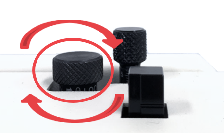
1. Lock the tension by turning the pressure lock clockwise.
 |
| When using endmill/ V-cutter etc |
2. Turn the cutting nose counterclockwise to align it to the tool hole.
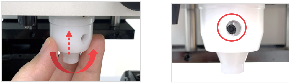
3. Replace the tool with a cutting tool.
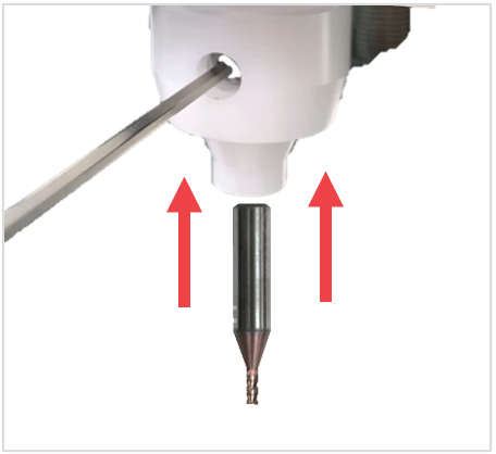
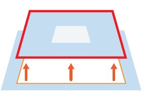
4. Put a flat plate (like a ruler) under the cutting nose (as shown in the picture below) then unscrew the tool fixing screw with a 2mm wrench. Lower the tool until it touches the plate then secure the tool in place.

5. Press on the keypad to enter  [MENU] mode. Select a [1. Tool Change] then press
 button to measure tool height.
6. Set the cutting clamp then secure the material to cut on the clamp.
Program
- Click
 Text Input button on the toolbar to enter the text input mode then click at any target area to enter text.
- After entering the text, click
 Selection on the toolbar to select the text and designate the font.
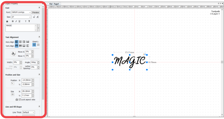
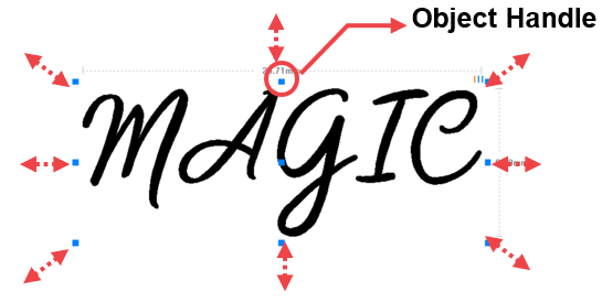
Adjust the text according to the desired size. Use the object handle (shown in the picture below) or go to object property window.
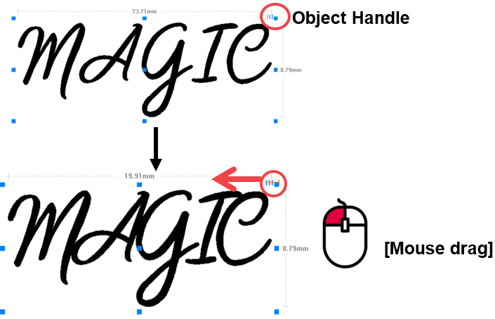
- Drag with the mouse the text gap adjustment handle (shown in the picture below) to narrow or widen the gap between the characters.
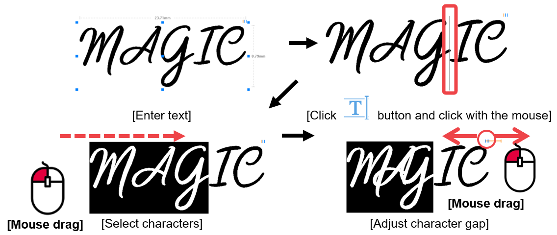
If the gap in between each character is partially adjusted, click Text Input button then drag the mouse to select the characters. Drag the text gap adjustment handle with the mouse then adjust the gap.
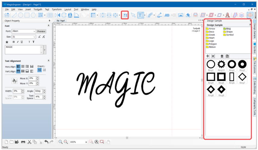
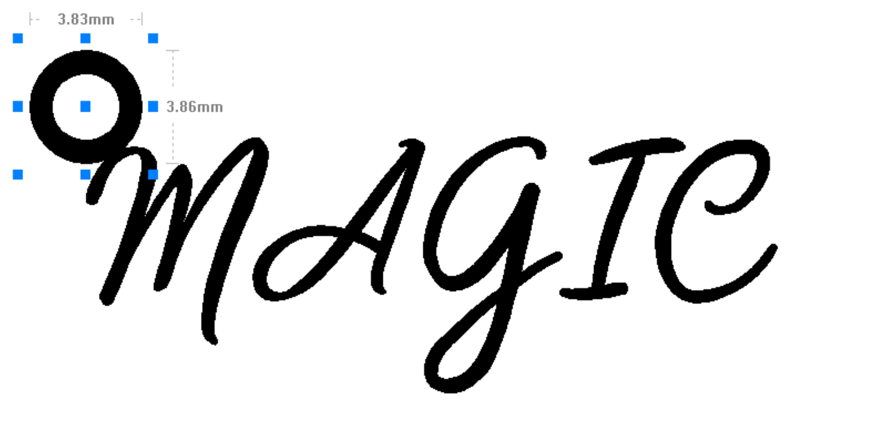
- Insert a ring design that matches your characters from the design sample section.
*Design sample: Click or Menu → View → Design sample.
- Double-click the chosen ring design then designate its location on the work area.
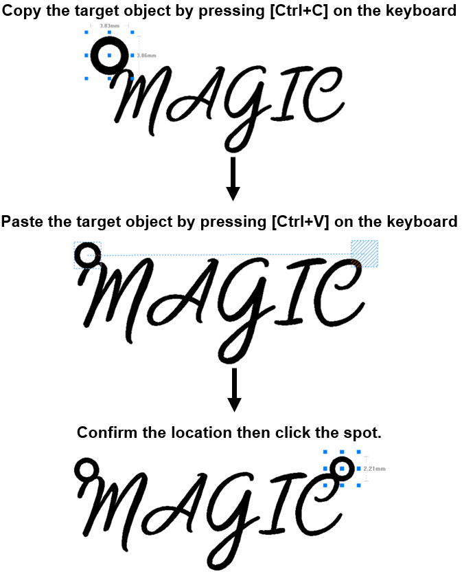
6. Copy and Paste the ring design to reveal a guideline for the location of the ring. Adjust the location, then left-click with the mouse.
- Select all the objects, then right-click to see the menu then select Group.
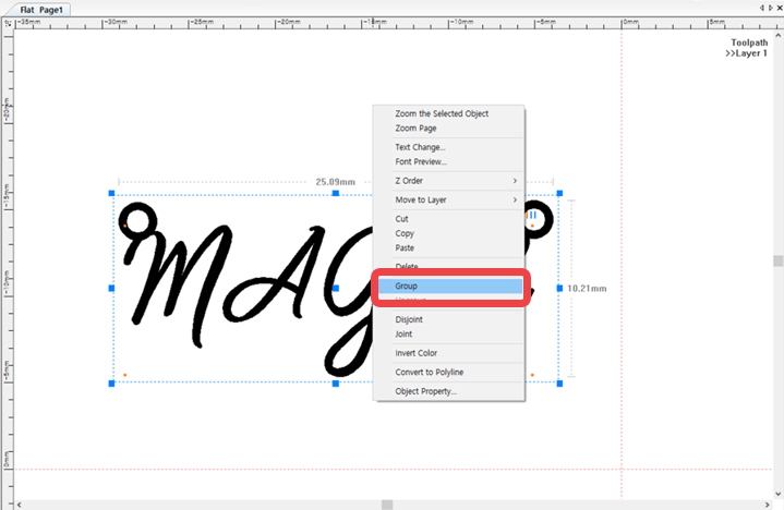
✽Select all objects: Drag the objects with the mouse or select Menu → Edit → Select All.
- Upon completing the design, click
 Cut-Out Toolpath.
- Once the “Cut-Out” window appears (as seen in the figure below), select the tool to be used for cutting. Enter the material’s thickness and other options then click “Create Toolpath.”
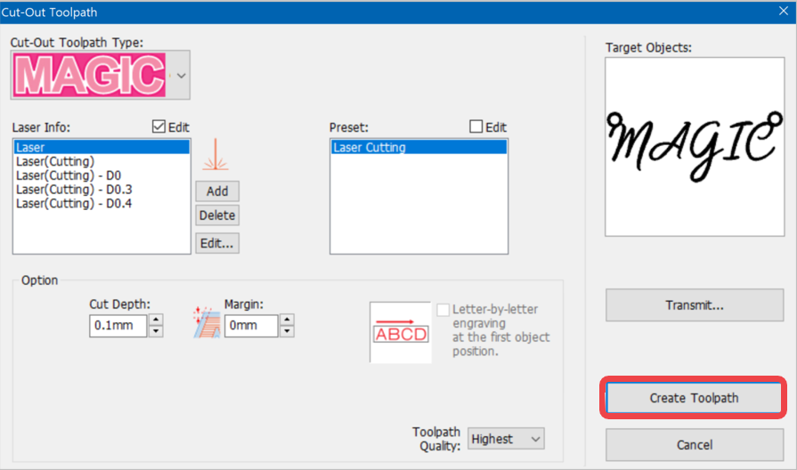
| Option | Depth | Designate the thickness for cutting. The material may be in a slanted or bent form. If so, the depth should be at 0.1-0.2 mm deeper than the thickness of material for perfect cutting. This option value is disabled for input because the depth is automatically calculated by “Plate Thickness”, “Extra Cut Depth” option. |
| Z pitch | Designate the depth when cutting the engraving depth little by little. This option is necessary when cutting thick materials with a thin tool.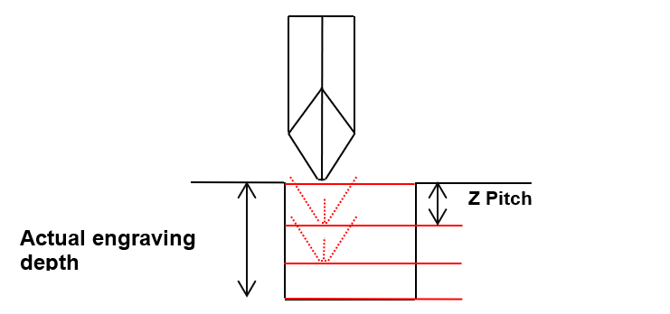 |
|
| Plate thick | Enter the measured thickness of the material. Cut depth and Z pitch value is automatically calculated by this value. | |
| Extra cut depth | Material might usually be bent or slanted. Thus, the cut depth should be at 0.1-0.2 mm deeper than the thickness of the material for perfect cutting. This designates extra depth for perfect cutting. | |
| Z pitch count | Z pitch value is automatically calculated by this value. | |
| Speed | XY speed | Designate a speed at which XY axis will move during the cutting. |
| Z speed | Designate a speed at which Z axis will move during the cutting. | |
| Move option | Z clearance | This designates the height to be applied for the clearance between the tool and the surface of material when moving to another engraving location.
When moving to another engraving location, it is necessary to lift Z axis to prevent the tool from coming in contact with the material surface before moving. 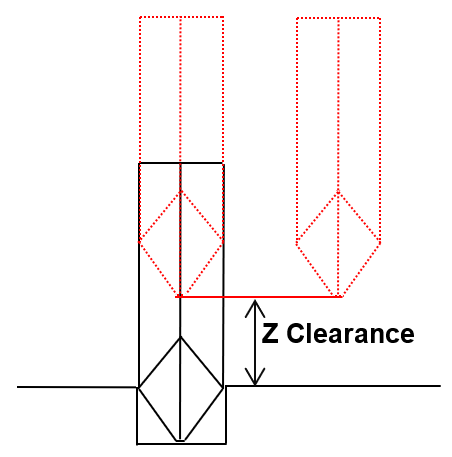
|
| Z dwell time | This designates no-load rotation time of end-mill and V-cutter after they reach the target depth and before moving to X, Y axis point. It is possible to damage the tool as rotation speed reduces while engraving. Set up the Z-dwell time to recover the full rotation speed before engraving. ✽Recommended time: 0.5 ~1 second. |
- “Toolpath” is created.
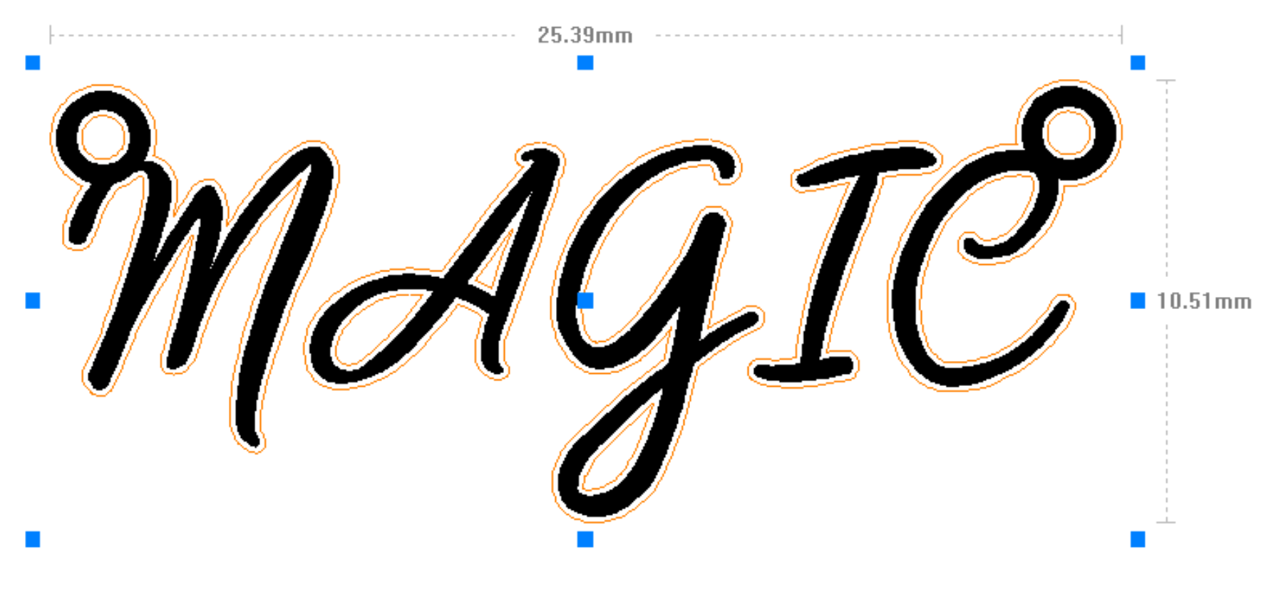
- After creating the toolpath, set the laser marking option then click
 Engraver button.
- Once “NC Output” window appears, specify how the engraving material is measured then click “Start Engraving” button.
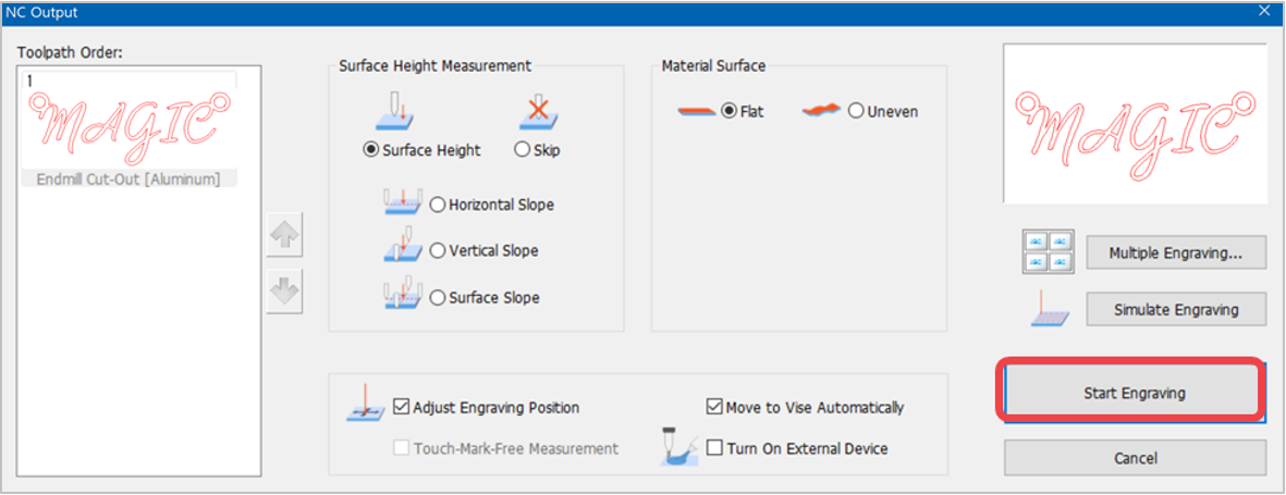
| Surface Height | Measure material height only.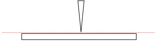 |
| Horizontal Slope | Measure material’s horizontal slope.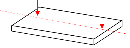 |
| Vertical Slope | Measure material’s vertical slope.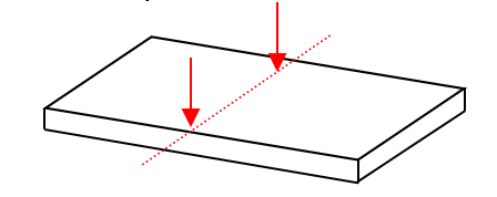 |
| Surface Slope | Measure material’s top, bottom, left and right slope.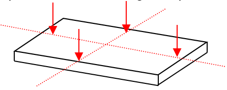 |
| Skip | Skips material’s height measurement and allows the use of the previous height measurement data if the material has not been removed from the clamp during the previous engraving process. |
| Adjust Engraving Position | Select this option to re-adjust the engraving location. The laser pointer then adjusts to the engraving location before engraving. If this option is not selected, engraving process will initialize immediately. |
| Move to vise automatically | Move automatically to the flat or rotating vise based on the selected template. |
- Once the tool is positioned to the center of the material and the laser pointer turns on, use the direction key buttons to position the laser pointer to the engraving area. The area that the laser pointer points to is where the actual engraving takes place.
 |
Press the direction key buttons to move the laser pointer to the left, top, right and bottom areas of the engraving area. (Long press to move the laser pointer farther). Check if the laser pointer points to the area on the material where you want to engrave. If the laser pointer is out of range, adjust the position using the direction keys.
The laser pointer automatically points to the area where marking takes place (based on the target location on the work area). When the direction key is pressed, the laser pointer moves to the area to be marked (left, top, right or bottom) from its target location. If the marking area needs to be adjusted to the left, press  key to move the pointer to the left. 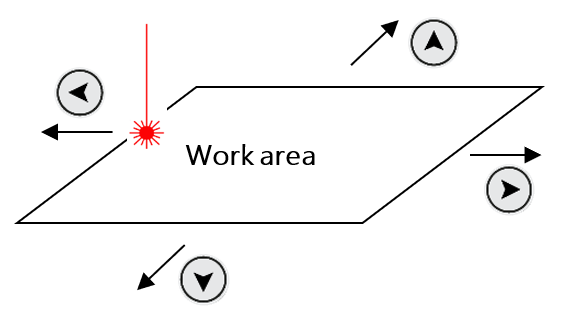 |
- After positioning the laser pointer and determining the location of the engraving area, long-press and hold
 button (for more than 3 seconds) until it beeps to confirm that the machine is ready to engrave.