[MAGIC-S7] Installation
Contents
- 1. Machine Installation How to install the machine
- 2. Program Installation How to install the software
- 3. Front Cover How to install the front cover
- 4. IO Port
- 5. Back cover How to install the back cover
- 6. Operation of the Marking Machine How to operate
※Please follow the instructions below for proper installation of the machine, software and other devices.
※The software program requires Windows OS 7 or higher.
1. Machine Installation
MAGIC™-S7 cannot operate alone as a desktop engraver. It cannot proceed to engraving and cutting operation without the use of a computer and a software.
The machine should be connected to a personal computer for the machine to operate. The software provided along with the machine must be installed to the computer to run the program for engraving, cutting and marking.
How to install the machine
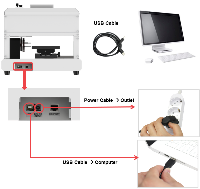
- To start the machine, plug its power cable into a grounded outlet. ※See precautions for use for safety.
- To connect the machine to the computer, plug in the USB cable on the back of the machine then on the computer’s USB port.
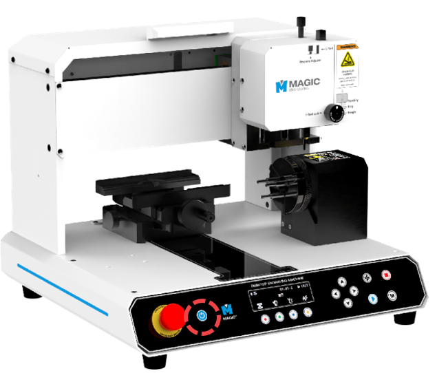
Power switch
 |
Power | Turns ON/OFF the machine. |
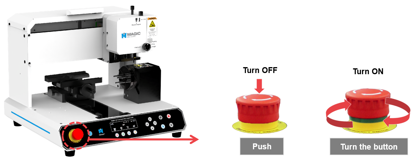
Emergency Switch
※If the machine won’t turn on, check the emergency switch.
2. Program Installation
[System requirements]
-Supported devices: PC
-Operating system: Windows 10 or higher
-Processor: Intel® Pentium® CPU or higher
-Memory: 4GB or more
[How to install the software]
1. Insert the USB into your computer`s USB port. A notification will pop-up on your screen regarding installation. ※USB is included in the package.
2. Follow the instructions below to install the software.
3. Follow the steps in order until installation is complete.
4. In case program installation won’t automatically run upon inserting the USB into your computer, go to My Computer’s USB drive then run Install program.
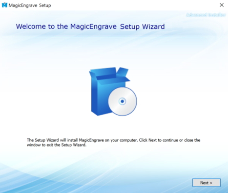
| 1. Setup wizard. |
 |
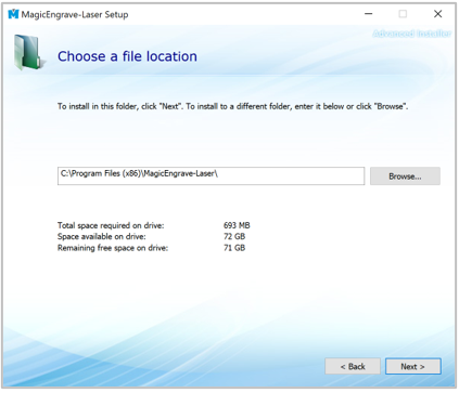
| 2. Select installation folder. |
 |
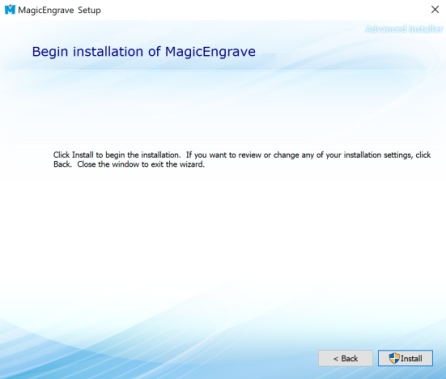
| 3. Confirm installation. |
 |
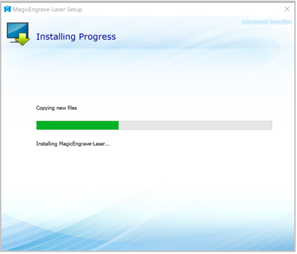
| 4. The file is copied onto the hard disk. |
 |
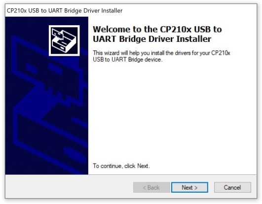
| 5. USB driver setup wizard. |
 |
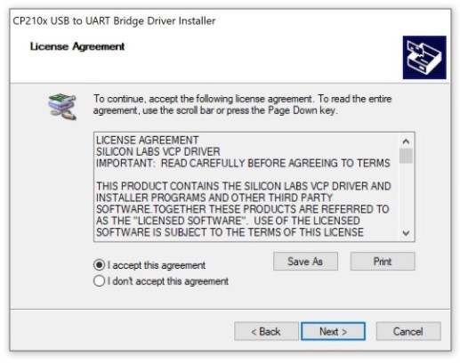
| 6. Check [I accept the agreement], then click [Next]. |
 |
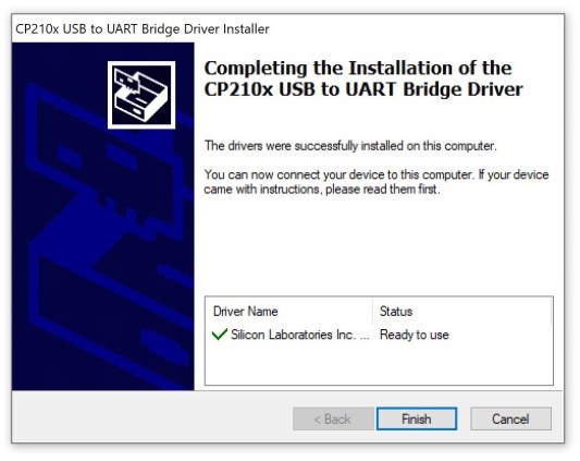
| 7. Check [Status: Ready to use], then click [Finish]. |
 |
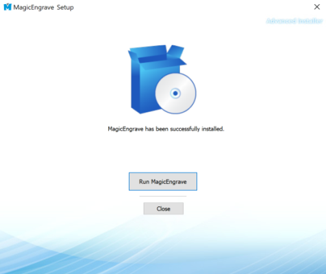
| 8. Click “Run MagicEngrave” button to complete program installation. |
 |
- Program Description
Once the installation is completed, the following icon will appear on your desktop. The description of the icon is as follows:
 |
As a design & marking software program, it features the following functions: marking design, marking option, Toolpath setting, transfer of Toolpath data. |
3. Front Cover
※Optional device; sold separately
How to install the front cover
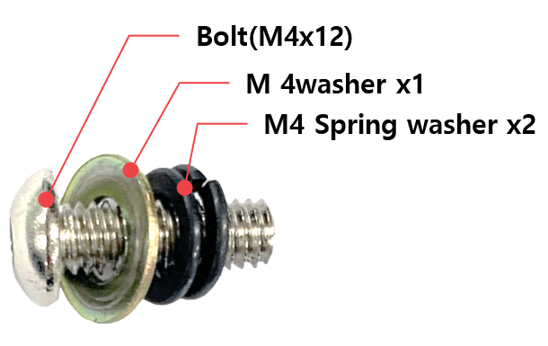
- Set the Bolt (M4x12) – M4 Washer – M4 Spring washer x 2 in order.
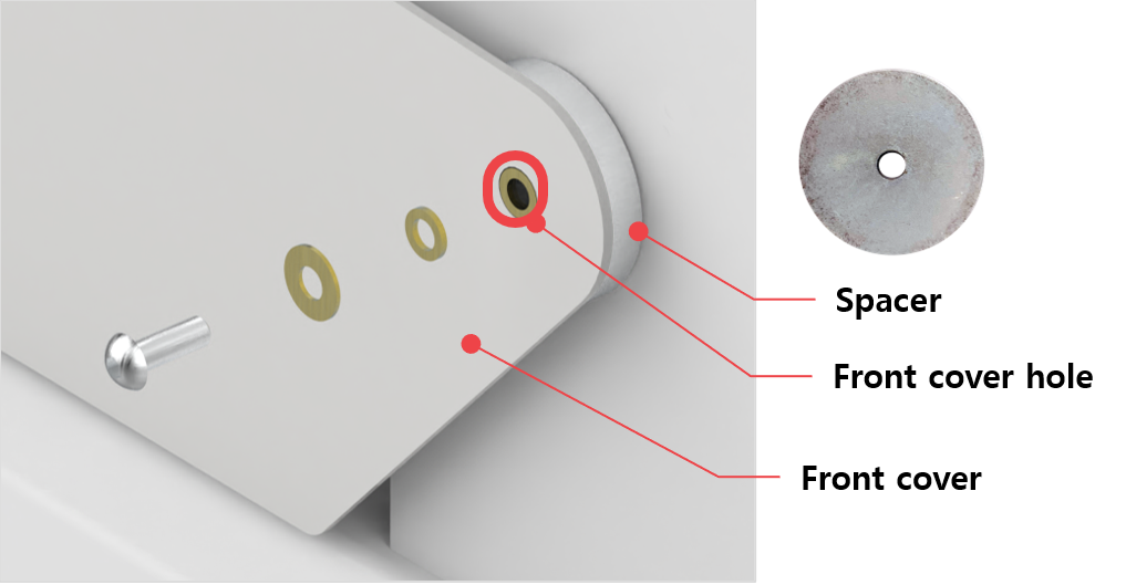
- Secure the step 1 with spacer. Secure the spring washer so that it fits into the front cover hole.
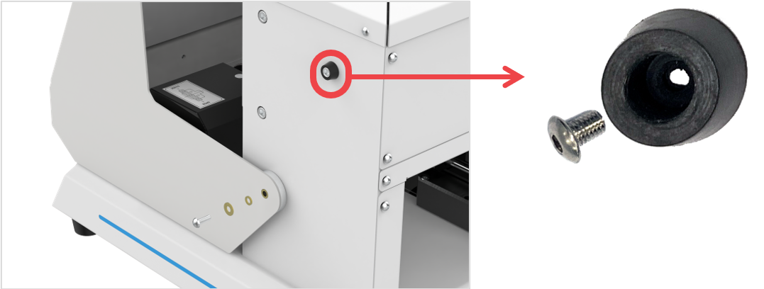
- Secure the cover stopper with bolt (M4x6).
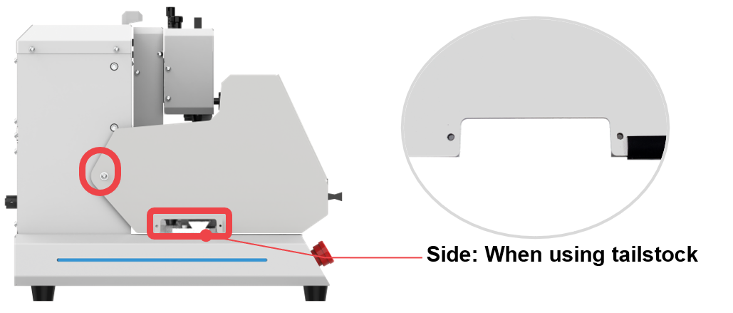
- Secure the other side in the same way.
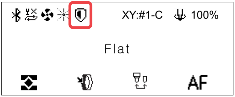
5. To enable Front Cover function, press  button on the keypad to enter MENU. Then, select 11. Front Cover option on the menu. Front Cover icon will be displayed on the LCD screen (as shown below) once it’s activated.
- Check the positioning of the head and the clamp. Front Cover open and close function is disabled when the head is positioned at the right end (of the machine) and the clamp at the front.
How to position the head and the clamp
-Standby mode: Press  button on the keypad to move the head and the clamp to a position where the Front Cover can be opened and closed.
-Auto-positioning of the head and the clamp: The head and the clamp are automatically positioned upon completion of initial marking (i.e., when the engraving operation is completed).
4. IO Port
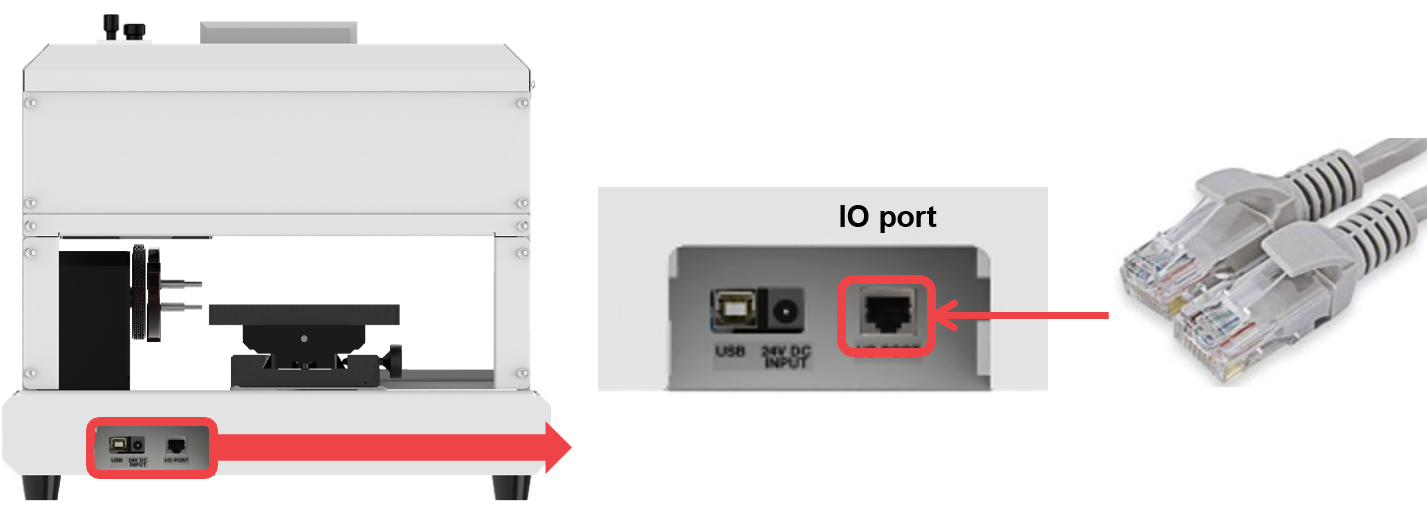
| OUT | 5V DC OUT | Requires a DC 5V output to connect. |
| IN | START/STOP | Starts or stops engraving operation when DC 5V is connected. |
| OUT | VACUUM ON/OFF | Chip collector ON/OFF output status: DC 5V output: ON; GND output: OFF |
| OUT | Universal Output | Universal output port for DC 5V output and external devices. |
| IN | Serial Communication Transmission | Receives serial communication from external devices. |
| OUT | Serial Communication Transmission | Transmits serial communication from external devices. |
**IN: Signal received by the machine
5. Back cover
-Optional (Sold separately)
| Back Cover (CP-253) |
 |
1EA | Back Port Cover |
| Square Magnet |  |
2EA | To secure the back cover. |
| Bolt (M3x8mm) |
 |
3EA | To secure the square magnet. |
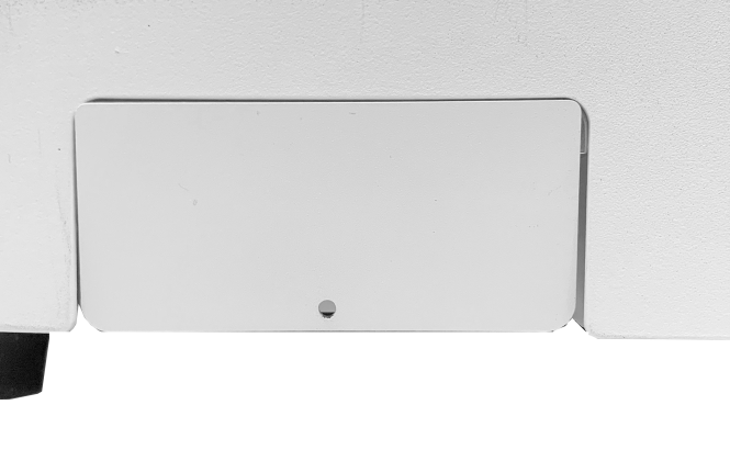
- Assemble the back cover then attach it to the back side of the machine.
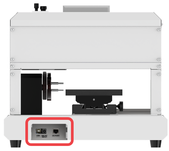
- Insert the bolt into the square magnet then screw it into the machine.
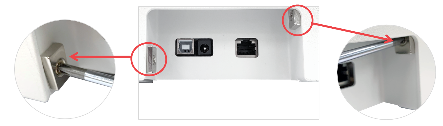
- Attach the back cover. The back cover is secured by the square magnets.
6. Operation of the marking machine
MAGIC™-S7 performs self-diagnosis upon turning ON. During self-diagnosis, the machine checks the following in order:
Self-diagnose Procedures
- If a certain axis is detected by the sensor, it moves away from the detected area.
- Checks probe sensor and returns to the Origin point
- Checks Z-axis sensor and returns to the Origin point
- Checks Y-axis sensor and returns to the Origin point
- Checks X-axis sensor and returns to the Origin point
- Confirmation sound and standby
If no problem is found, it goes into standby mode with a confirmation sound.
Marking Procedures
1. Turn on the marking machine.
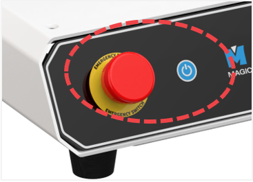
※ If the machine does not turn on, check the emergency switch.
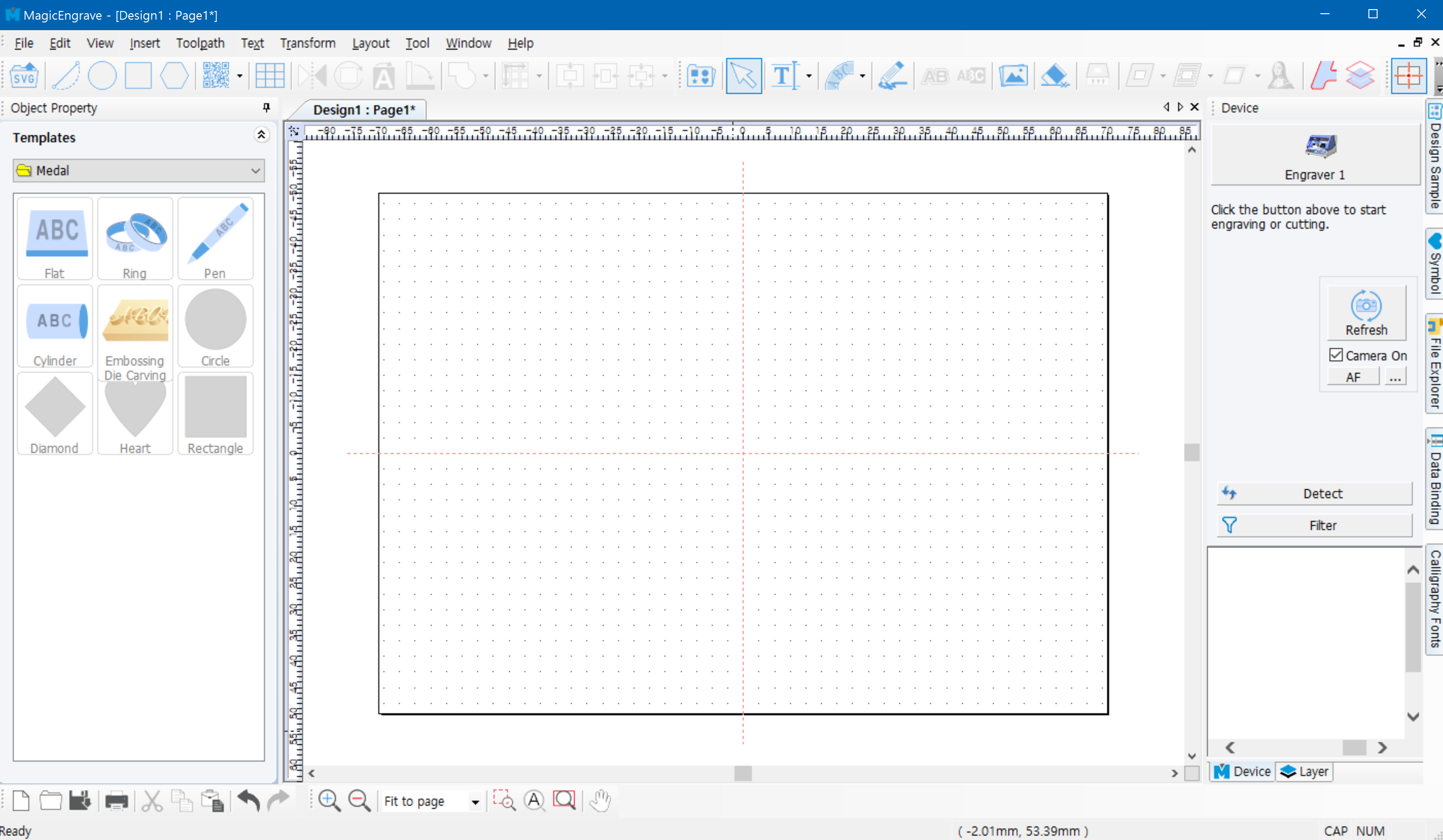
2. Run the program to connect it to the machine.
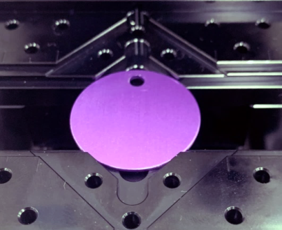
3. Place your material on the work area.
4. Make your design then create a toolpath.
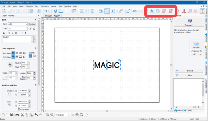
5. Click the Machine button to send the marking data.
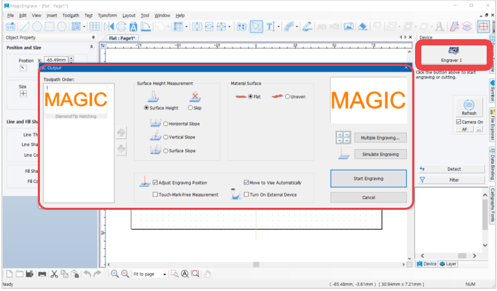
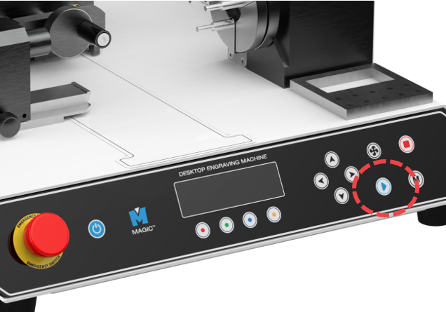
6. Press start  button on the machine to begin the engraving process.